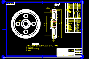

动力输出总成的设计(720转/分)
摘 要
动力输出轴是拖拉机的重要工作部件,动力输出主要用于拖拉机在行进中输出发动机动力以驱动农机具,如割草机、喷药机等。动力输出总成的设计是基于减速增扭的原理。动力从变速箱引出,再进过一对大小齿轮减速,转速减小的同时,扭矩成比例的增加。动力输出没有标准的设计过程,主要根据变速器和减速器的设计,确定齿轮的传动类型、传动关系、受力分析、建立数学模型。依据传统的设计方法,本着半经验半理论的设计原则通过类比的方法,参考已有车型的动力输出的设计过程,然后验算零件的强度和机械应力情况,最后确定了采用半独立式的动力输出机构方案,动力直接从发动机的曲轴引出,这种输出类型现在被广泛使用,特别受到欧美的青睐。本次设计采用的主动的直齿滑动齿轮啮合,主动齿轮可以在高速轴上滑动,以提供啮合和分离的选择。这种设计最大的优点是结构简单,便于安装和维修。
而且为了避免动力输出轴头在高速旋转下危及人身的事故发生,本次设计专门设计了动力输出轴保护罩,保证外露的高速旋转部件不会伤害人,提高了使用的安全性。
关键词:动力输出轴,半独立式,主动齿轮,从动齿轮
POWER TAKEOFF SHAFT DESIGN(720r/min)
ABSTRACT
Power take off shaft is an important part of the tractor, PTO shaft provides a means to drive the machines that are being towed by the tractor, Take mower and manure spreaders for example.
The PTO shaft operates on the principle of reducing the PTO shaft speed, before the drive from the transmission is applied. At the same time ,the PTO shaft increases the torque ,for when speed is lost through gears, torque is gained in the same proportion . According to the design of the transmissions in consideration of the simplicity and reliability. According to the traditional mean of design, part experience and theory and analogism. We firstly chose gear type, make selection of the gear parameter, then establish the mathematic model dose the type of the being.
In this thesis, we dose semi-independent type. This type of PTO shaft is popular not only in our country, but also in Europe. The merit of this type is outstanding, We choose spur gear to transmit the drive.the driving gear can be slid along the splines on the internal end of shaft and into mesh with driven gear. The means of this type is easy for fixing and mending.
To avoid the accident of the wound from the revolving of the end of PTO shaft, the shaft and universal joint of PTO should be guarded by commercially available shields ,which cover moving part, so it will improve the softy.
Key words:PTO shaft, semi-independent, driving gear, driven gear
目 录
第一章 绪论…….. .. .. .. .. .. ……………………1
- 1.1拖拉机发展概述……………………….1
- 1.2动力输出总成的概述……………………….3
- 1.3拖拉机工作速度匹配………………………5
- 1.4 动力输出轴的转速配置………………………5
- 1.5动力输出轴性能………………………6
第二章 动力输出总成齿轮主要参数的确定… .. .. .. .. …..8
- 2.1 齿轮的概述…. .. .. .. .. …………………..8
- 2.2 方案一设计.. .. …………………………..8
- 2.2.1 方案一齿轮计算 . ………………. ……8
- 2.2.2 方案一轴设计……………………. …..9
- 2.3 方案二设计.. …………… .. ……………12
- 2.3.1 方案二齿轮设计…………………. ……12
- 2.3.2 齿轮变位设计…………………. …….. 15
- 2.3.3 齿轮重合度的设计…………………. ….17
第三章 动力输出总成轴承的计算………………….19
- 3.1 轴承的概述.. .. .. .. ………………………19
- 3.2 轴承的计算……………………………19
第四章 轴的校核计算…………………………..21
- 4.1 高速轴设计…. .. .. .. …………………….21
- 4.2 低速轴设计…. .. …………………………23
第五章 花键的计算……………………………..26
- 5.1 低速轴花键设计. … ……………………….26
- 5.2 高速轴花键设计……………………………27
- 5.3 连轴器花键设计…………………… …….. 28
第六章 控制机构设计……………………………30
- 6.1 自锁弹簧的设计…. .. …………………….30
- 6.2 操纵机构位置的设计………………………..31
第七章 动力输出轴的加工方法…………………..34
第八章 使用与保养………………….35
第九章 结论…………………………………..37
参考文献………………………………………..38
致谢……………………………………………40


